When setting up your Viofo 229 dual dashcam system for parking mode, one crucial aspect is ensuring that it powers up correctly and switches between normal mode and parking mode efficiently. In this guide, I’ll share how I set up my system with the Viofo HK4 hardwiring kit and measure the necessary signals for proper operation. I then used a LiFePO4 external battery to power the dashcams. I will highlight essential power considerations to keep your cameras running smoothly in parking mode.
What is Viofo 229 Parking Mode?
The Viofo 229 parking mode is a feature designed to keep your dashcam recording even when the car is parked and turned off. The dashcam will automatically switch to parking mode when the vehicle’s ignition is off. Using an external LiFePO4 battery allows the Viofo 229 to monitor activity around the car without draining the main battery.
How to Set Up Viofo 229 Parking Mode with the HK4 Hardwiring Kit
The Viofo HK4 is a hardwiring kit that connects directly to your vehicle’s fuse box and provides a reliable power source for your dashcam system. The kit consists of three primary input wires:
- +12V (Power)
- GND (Ground)
- Ignition (ACC)
This kit connects to your Viofo 229 system via a USB-C cable, powering both the front and rear cameras.
Measuring the Signals
To understand how the Viofo 229 parking mode works, I used a USB-C 24-pin passthrough board.
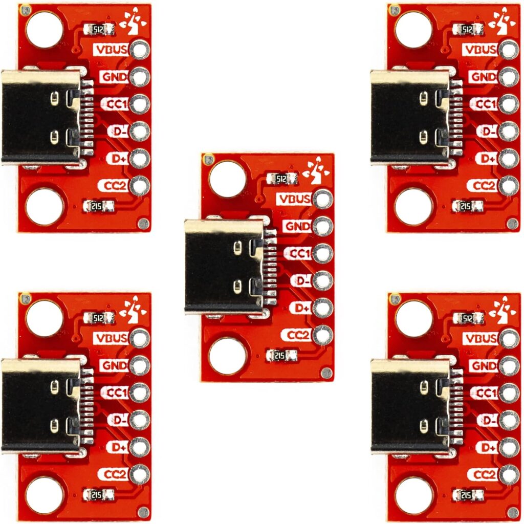
This enables me to measure the key signals between the hardwiring kit and the dashcam. With a supply voltage of +12.5V, I measured each pin with a multimeter, focusing on the following signals:
- VBUS – This is the +5V power line used by the Viofo 229.
- GND – This is the ground line.
- CC1 and CC2 – These USB signals help determine the state of the ignition.
Understanding the Role of CC1 and CC2
The Viofo 229 uses the CC1 and CC2 signals to determine when to enter parking mode or normal mode. These signals are part of the USB-C standard. The Viofo utilizes these signals in a different way:
- A high voltage (3.3V to 5V) on CC1 or CC2 signals the camera to enter normal recording mode.
- A low voltage (0V) on these signals triggers the dashcam to enter parking mode.
Here is a table showing how the signals change when the ignition is on and off:
| USB-C Pin No | Upright | Flipped | |||
| ACC = 12 V | ACC = 0 V | ACC = 12 V | ACC = 0 V | ||
| A4 | VBUS | 5.26 | 5.26 | 5.27 | 5.26 |
| A5 | CC1 | 0 | 0 | 4.97 | 0 |
| A9 | VBUS | 5.26 | 5.26 | 5.26 | 5.26 |
| B4 | VBUS | 5.26 | 5.26 | 5.26 | 5.26 |
| B5 | CC2 | 4.97 | 0 | 0 | 0 |
| B9 | VBUS | 5.26 | 5.26 | 5.26 | 5.26 |
Power Supply Considerations
While configuring the Viofo 229 for parking mode, it’s essential to ensure that the power supply can handle the extra demands of both cameras, especially when WiFi is enabled. I initially used an Anker cigarette adapter rated at 5V, 2.4A per port to power the dashcam system. While it worked initially, the cameras kept resetting once I turned on WiFi.
Upon further testing, I realized that the Anker cigarette plug adapter didn’t provide a consistent power supply. Likely, this is due to lower efficiency or an insufficient amperage output. When I switched to the Viofo-provided power adapter, the system worked flawlessly, with no resets.
This experience serves as a reminder: always be cautious about the power ratings of your cigarette plug adapters. Ensure it can handle the current draw, especially when WiFi is active.
Conclusion: Ensuring Stable Power for Viofo 229
You now have a good understanding of the signals that command the Viofo 229. With this knowledge, you can supply an external battery and power the dashcams.
Enjoy reliable, round-the-clock protection for your vehicle.